Automated Robotic Vehicle Steering System
Motor and Controller Enclosure
These two housing components together were considered one of, if the not the, most important aspect of the entire design. These had to effectively hold the two most expensive and important parts in such a manner that allowed the support structure to be attached securely. Then the motor drive shaft had to connect with the steering wheel and be able to apply the necessary torque without any restrictions.
Motor Dimensions
Motor Housing


Controller Dimensions

Controller Housing


Steering Wheel Mounting Plate


The controller housing is made up of two pieces of mild steel along with two pieces of 1" x 1.75" solid pine wood seen in Figure 4. All of these materials came from recycled goods that were provided by the ECE machine shop. The mild steel was needed for cooling the controller via conduction and the solid pine wood provided a substantial amount of weight in order to effectively counteract the weight of the motor. Figure 7 shows that the useful area in the housing was 7" x 6" x 1.75" and provided ample amount of room for the controller at 5.5" x 5.5" x 0.98".
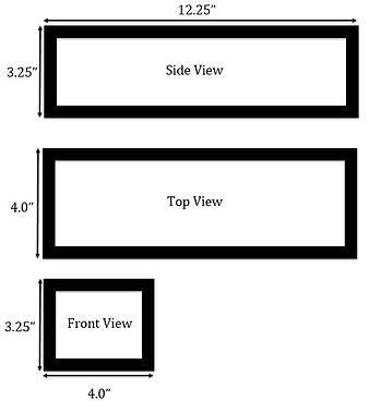
The motor housing carried the bulk of the weight and was decided on to be made of 1/2" plywood for rigidity along with a 1/8" Aluminum sheet attached to the front for mounting the motor. The dimmensions of the box were chosen to be 12.25" x 4" x 3.25" which is slightly bigger than the motor's width and height, 2.05" x 2.25". The reason for this is because the utility vehicle would be on extremely rough terrain and it would be undesirable for the motor to be bouncing against the sides of the enclosure. The length of 12.25" is much greater than the length of the motor at 7.16" but was chosen so that the controller housing could be mounted further behind the motor in order to offset the motor's heavy weight.
The steering wheel mounting plate was carefully decided on so that it could be precisely adjusted to any range of utility vehicle steering wheel sizes. The material was recycled mild steel and provided a rigid, lightweight design. The straps seen in Figure 9 were used for their ratcheting ability and could hold up to 500lbs before failing. The mounting plate was implemented and tested in the Polaris Ranger EV and Kubota RTV 1100 shown in Figure 9. The three long sides of the plate are 8" and
Appendix B
-
Creating a Robotic Steering System in five short months proved that the road to "self-driving" cars is not an extremely long one to travel. Although this current design is a very rudimentary effort at achieveing this goal, it still shows that creating the actual robotic system in charge of the mechanical control of vehicles is extremely plausible and can be cost efficient. The cost efficient aspect of this design is the most important because in order to create a business around a product it must set a reasonable price for consumers and government to implement. It was also recognized that many people do not like the idea of robotic systems controlling their life so it was carefully decided that our system would be quickly and easily removable. Many of the products used came from recycled materials such as the mild steel from old CPU housings and discarded PVC piping. After the lifecycle of this system has come to an end these parts can be reused and recycled for construction of more advanced systems or something entirely different.
-
Whenever it was felt that an amendment had to be made to the design or an error in had arose the group would get together to make sure that it could not be quickly fixed. In order to decide this we would carefully analyze the purposed problem or error and collect as much data as we could on it to see if others had encountered a similar issue. If this was the case we would use advice, data and references from others in order to draw final conclusions on our particular situation. When we encountered unique data or errors, which was the case most of the time, we called upon our own engineering experience to find quick and logical solutions.
authored by: Robert Hoffman
the other three short sides are 2" long. This allows the plate to be big enough to support the shaft mount but small enough to fit in any steering wheel. The shaft mount can be seen connected to solely the motor drive shaft in Figure 8 and then bolted to the mountin plate in Figure 9. The straps currently in place are 11" in length but straps up to 36" can be implemented if necessary.
Figure 2. Motor Dimmensions
Figure 1. Motor Housing Implementation
Figure 3. Motor Housing Dimmensions
Figure 4. Controller Housing Implementation
Figure 5. Controller Dimmensions from a Top View
Figure 6. Controller Dimmensions from a Side View
Figure 7. Controller Housing Dimmensions
Figure 9. Steering Wheel Mounting Plate Implemented in Kubota RTV100
Figure 8. Motor Housing with Drive Shaft Mount Attached